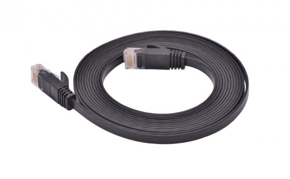
 Wired Ethernet adapters typically have an eight position, eight conductor (8P8C) connector informally known as an RJ45 connector, which looks like a large telephone jack.
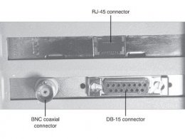
Fast Ethernet and gigabit Ethernet twisted-pair cables use these connectors, but you might still see older adapters that support a single BNC connector (for Thinnet coaxial cables) or a D-shaped 15-pin connector called a DB-15 (for Thicknet coaxial cables). Some older 10 Mb/s adapters have a combination of two or all three of these connector types; adapters with two or more connectors are referred to as combo adapters. Token-Ring adapters can have a 9-pin connector called a DB-9 (for Type 1 STP cable) or sometimes an 8P8C (RJ45) jack (for Type 3 UTP cable). The following image shows all three of the Ethernet connectors.
Note: Although RJ45 is the common name for the UTP Ethernet connector, this is a misnomer. The correct name for the connector is 8P8C, which indicates an 8-pin, 8-conductor connector. The actual RJ45S connector is an eight-position connector but is used for telephone rather than computer data. An RJ45S jack has a slightly different shape than the connector used for Ethernet, and it includes a cutout on one side to prevent unkeyed connectors from being inserted into it.
For drawings of the true RJ45S jack and other telephone jacks, see
Ethernet NICs made for client-PC use on the market today are designed to support unshielded twisted-pair (UTP) cable exclusively. Cards using BNC or DB-15 connectors would be considered obsolete.
For maximum economy, NICs and network cables must match, although media converters can interconnect networks based on the same standard, but using different cable.
Network Cables for Wired Ethernet
Originally, all networks used some type of cable to connect the computers on the network to each other. Although various types of wireless networks are now on the market, many office and home networks still use twisted-pair Ethernet cabling. Occasionally you might still find some based on Thick or Thin Ethernet coaxial cable.
Thick and Thin Ethernet Coaxial Cable
The first versions of Ethernet were based on coaxial cable. The original form of Ethernet, 10BASE-5, used a thick coaxial cable (called Thicknet) that was not directly attached to the NIC. A device called an attachment unit interface (AUI) ran from a DB-15 connector on the rear of the NIC to the cable. The cable had a hole drilled into it to allow the “vampire tap” to be connected to the cable. NICs designed for use with thick Ethernet cable are almost impossible to find as new hardware today.
10BASE-2 Ethernet cards use a BNC (Bayonet-Neill-Concelman) connector on the rear of the NIC. Although the thin coaxial cable (called Thinnet or RG-58) used with 10BASE-2 Ethernet has a bayonet connector that can physically attach to the BNC connector on the card, this configuration is incorrect and won’t work. Instead, a BNC T-connector attaches to the rear of the card, allowing a Thin Ethernet cable to be connected to either both ends of the T (for a computer in the middle of the network) or to one end only (for a computer at the end of the network). A 50-ohm terminator is connected to the other arm of the T to indicate the end of the network and prevent erroneous signals from being sent to other clients on the network. Some early Ethernet cards were designed to handle thick (AUI/DB-15), thin (RG-58), and UTP (unshielded twisted pair) cables. Combo cards with both BNC and 8P8C (RJ45) connectors are still available on the surplus equipment market but can run at only standard 10 Mb/s Ethernet speeds.
The following figure compares Ethernet DB-15 to AUI, BNC coaxial T-connector, and 8P8C (RJ45) UTP connectors, and the one after that illustrates the design of coaxial cable.
Twisted-Pair Cable
Twisted-pair cable is just what its name implies: insulated wires within a protective casing with a specified number of twists per foot. Twisting the wires reduces the effect of electromagnetic interference (EMI, which can be generated by nearby cables, electric motors, and fluorescent lighting) on the signals being transmitted. Shielded twisted pair (STP) refers to the amount of insulation around the cluster of wires and therefore its immunity to noise. You are probably familiar with unshielded twisted pair (UTP) cable; it is often used for telephone wiring.The following image shows UTP cable; the one after that illustrates STP cable.
Shielded Versus Unshielded Twisted Pair
When cabling was being developed for use with computers, it was first thought that shielding the cable from external interference was the best way to reduce interference and provide for greater transmission speeds. However, it was discovered that twisting the pairs of wires is a more effective way to prevent interference from disrupting transmissions. As a result, earlier cabling scenarios relied on shielded cables rather than the unshielded cables more commonly in use today.
Shielded cables also have some special grounding concerns because one, and only one, end of a shielded cable should be connected to an earth ground; issues arose when people inadvertently caused grounding loops to occur by connecting both ends or caused the shield to act as an antenna because it wasn’t grounded.
Grounding loops are created when two grounds are tied together. This is a bad situation because each ground can have a slightly different potential, resulting in a circuit that has low voltage but infinite amperage. This causes undue stress on electrical components and can be a fire hazard.
Most Ethernet installations that use twisted-pair cabling use UTP because the physical flexibility and small size of the cable and connectors makes routing it easy. However, its lack of electrical insulation can make interference from fluorescent lighting, elevators, and alarm systems (among other devices) a major problem. If you use UTP in installations where interference can be a problem, you need to route the cable away from the interference, use an external shield, or substitute STP for UTP near interference sources.


