 Basic Theory:
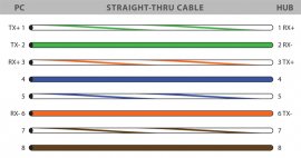
By looking at a T-568A UTP Ethernet straight-thru cable and an Ethernet crossover cable with a T-568B end, we see that the TX (transmitter) pins are connected to the corresponding RX (receiver) pins, plus to plus and minus to minus. You can also see that both the blue and brown wire pairs on pins 4, 5, 7, and 8 are not used in either standard. What you may not realize is that, these same pins 4, 5, 7, and 8 are not used or required in 100BASE-TX as well. So why bother using these wires, well for one thing its simply easier to make a connection with all the wires grouped together. Otherwise you'll be spending time trying to fit those tiny little wires into each of the corresponding holes in the RJ-45 connector.
T-568A Straight-Through Ethernet CableThe T-568A standard is supposed to be used in new network
installations. Most off-the-shelf Ethernet cables are still of the T-568B standard; however, it makes absolutely no functional difference in which you choose.
 T-568B Straight-Through Ethernet Cable
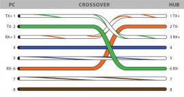
Both the T-568A and the T-568B standard Straight-Through cables are used most often as patch cords for your Ethernet connections. If you require a cable to connect two Ethernet devices directly together without a hub or when you connect two hubs together, you will need to use a Crossover cable instead.
RJ-45 Crossover Ethernet Cable
Cat5e Crossover Cables | Cat6 Crossover Cables
A good way of remembering how to wire a Crossover Ethernet cable is to wire one end using the T-568A standard and the other end using the T-568B standard. Another way of remembering the color coding is to simply switch the Green set of wires in place with the Orange set of wires. Specifically, switch the solid Green (G) with the solid Orange, and switch the green/white with the orange/white.
 How to Build an Ethernet Cable Instructions:
- Pull the cable off the reel to the desired length and cut using wire cutters or scissors. If you are pulling cables through holes, it's easier to attach the RJ-45 plugs after the cable is pulled. The total length of wire segments between a PC and a switch or between two PC's cannot exceed 100 Meters (328 feet) for 100BASE-TX and 300 Meters for 10BASE-T.
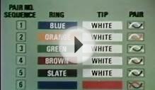
- Spread, untwist the pairs, and arrange the wires in the order of the desired cable end. Flatten the end between your thumb and forefinger. Trim the ends of the wires so they are even with one another, leaving only 1/2" in wire length.
 If it is longer than 1/2" it will be out-of-spec and susceptible to crosstalk. Flatten and insure there are no spaces between wires.
 - Hold the RJ-45 plug with the clip facing down or away from you. Push the wires firmly into the plug. Inspect each wire is flat even at the front of the plug. Check the order of the wires. Double check again. Check that the jacket is fitted right against the stop of the plug. Carefully hold the wire and firmly crimp the RJ-45 with the crimp tool.
- Check the color orientation, check that the crimped connection is not about to come apart, and check to see if the wires are flat against the front of the plug. If even one of these are incorrect, you will have to start over. Test the Ethernet cable.
YOU MIGHT ALSO LIKE


Share this Post
latest post
-
 Split Ethernet cable into two February 10, 2019
 -
 What is Ethernet Patch Cables? February 5, 2019
 -
 Military Fiber Optic cable January 31, 2019
 -
 Networking cable types January 26, 2019
 -
 Fluke Ethernet cable Tester January 21, 2019
 -
 Molex Fiber Optic cable January 16, 2019
 -
 Buy Ethernet Cables online January 11, 2019
 -
 Harford County cable Network January 6, 2019
 -
 Serial to Ethernet cable January 1, 2019